Function: The AND gate outputs a high signal (1) only when all its inputs are high
SYMBOL
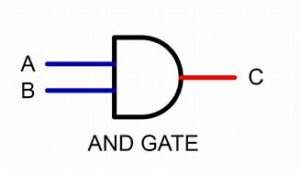
Truth table
| A | B | Y |
|---|---|---|
| 0 | 0 | 0 |
| 0 | 1 | 0 |
| 1 | 0 | 0 |
| 1 | 1 | 1 |
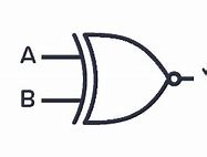
2. OR Gate
Function: The OR gate outputs a high signal if at least one of its inputs is high.
SYMBOL
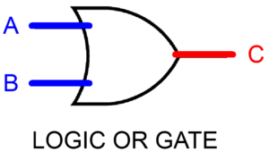
Truth Table:
| A | B | Y |
|---|---|---|
| 0 | 0 | 0 |
| 0 | 1 | 1 |
| 1 | 0 | 1 |
| 1 | 1 | 1 |
3. NOT Gate
Function: The NOT gate outputs the inverse of the input signal.
Symbol:
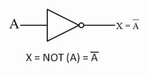
Truth Table:
| A | Y |
|---|---|
| 0 | 1 |
| 1 | 0 |
4. NAND Gate
Function: The NAND gate outputs a low signal (0) only when all its inputs are high. It is the inverse of the AND gate.
Symbol:
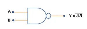
Truth Table:
| A | B | Y |
|---|---|---|
| 0 | 0 | 1 |
| 0 | 1 | 1 |
| 1 | 0 | 1 |
| 1 | 1 | 0 |
5. NOR Gate
Function: The NOR gate outputs a low signal if at least one of its inputs is high. It is the inverse of the OR gate.
Symbol:
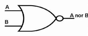
Truth Table:
| A | B | Y |
|---|---|---|
| 0 | 0 | 1 |
| 0 | 1 | 0 |
| 1 | 0 | 0 |
| 1 | 1 | 0 |
6. XOR Gate
Function: The XOR (Exclusive OR) gate outputs a high signal if the inputs are different.
Symbol:

Truth Table:
| A | B | Y |
|---|---|---|
| 0 | 0 | 0 |
| 0 | 1 | 1 |
| 1 | 0 | 1 |
| 1 | 1 | 0 |
7. XNOR Gate
Function: The XNOR (Exclusive NOR) gate outputs a high signal if the inputs are the same. It is the inverse of the XOR gate.
Symbol:
Truth Table:
| A | B | Y |
|---|---|---|
| 0 | 0 | 1 |
| 0 | 1 | 0 |
| 1 | 0 | 0 |
| 1 | 1 | 1 |
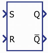
SR (Set-Reset) Flip-Flop:
Operation: Has two inputs, S (Set) and R (Reset), and two outputs, Q and Q’ (Q prime). When S is 1 and R is 0, Q is set to 1. When S is 0 and R is 1, Q is reset to 0. When both S and R are 0, the state of Q remains unchanged. Both S and R being 1 is typically an invalid state.
Symbol:
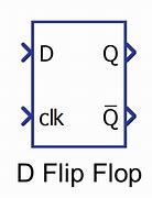
D (Data or Delay) Flip-Flop:
Operation: Has a single input D and a clock input. The output Q takes the value of D at the moment of the clock edge (rising or falling, depending on design).
Symbol:
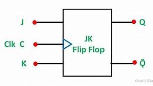
JK Flip-Flop:
Operation: Has two inputs, J and K, and a clock input. When both J and K are high, the output toggles. When J is high and K is low, Q is set. When J is low and K is high, Q is reset.
Symbol:
T (Toggle) Flip-Flop:
Operation: T flip-flop toggles its state when the T input is high at the clock edge
Symbol:
